This piece is a subsection of the notes for BT engineers and is published here to inform those boaters who want to learn more about the workings of the system and more importantly the injector pumps.
I am happy to email a MSWord file of this document that has better pictures upon emailed request.
THE C.I. FUEL SYSTEM
OUTLINE
There are three main type of C.I. fuel system in use on light vehicle, each taking its name from the type of injector pump used:-
Large engines may also use a system known as UNIT INJECTOR, CUMMINGS (after the major developer) or PRESSURE TIME
Apart from the large engine system above the systems have many components and principles in common so we will study the systems by covering the common parts first and then the injector pumps. The common parts are:-
Industrial installations often use a DAY TANK. This is a small, high level tank that feeds the fuel system by gravity, and is kept full by either an electric or manual pump from a bulk supply tank. This may or may not be in place of the engine lift pump.
Typical diagrams for both the pumped and day tank systems for inline or individual injector pumps are shown below.
You will see that the only difference is how the fuel gets to the injector pump. There will always be "filters" between the tank and injector pump.
Remember that the engine converter may have found it easier to retain the engine lift pump.
The other diagrams
Having shown you the differences between a day tank system and a lift pump system we assume you will not need the day tank diagram for the other injector pump diagrams. Study the following diagrams, remembering they could also be day tank systems, and note the common features.
The only changes on the diagram above from the INLINE PUMP block diagram are:
Now the Rotary Pump Block Diagram
The Rotary Pump diagram looks a lot simpler, this is because it is typical of a private car. When diesel engines were mainly used in commercial vehicles that were very likely to draw their fuel from private storage tanks it was important to try and protect the system from the dirt and water in badly maintained storage tanks. Private cars usually draw their fuel from filling stations that (should) ensure their tanks are clean and free from water, thus the primary or chassis filter can be dispensed with.
The rotary pump is a modern design that employs an internal pump that is powerful enough to draw fuel from the vehicle tank, thus the lift pump is no longer needed. It is also designed to continuously return a certain amount of fuel, from the injector pump, back to the tank. This makes it self-bleeding as far as the low-pressure side of the system is concerned.
A rotary pump on an industrial engine may still use a lift pump and primary filter so the diagram would be similar to the inline pump.
AIR IN FUEL
If any air gets into the injector pump the engine is very likely to stop (unless the pump is self bleeding) because it is easier to compress the air than it is to raise the fuel to injection pressure.
This is why whenever a C.I. engine runs out of fuel or has a fuel system component changed it has to be bled - that is a procedure to remove the air. You will need to have bleeding a diesel engine demonstrated to you.
THE COMPONENTS
The fuel tank
The fuel tank will be very similar to a petrol tank, having a breather and baffles etc. The only difference may be in internal coating or material because diesel fuel has a different chemical effect to petrol.
If the tank is exposed to air flow it may also be insulated with some form of jacket, this helps the fuel keep warm to prevent it WAXING (see later section) in cold conditions and blocking the filters. In extreme conditions the jacket may be fitted with an electric heating element.
The tank – be it main or day – should have a drain tap fitted to its lowest point. This is to allow a sample of fuel to be drawn off & inspected for water contamination.
The pipes
The injector pipes are special small bore/thick wall steel pipes so they withstand the high pressure, their shape is a design feature to ensure even fuel delivery to the cylinders so they should not be bent. The pressure pulses can force the pipe out of the factory swaged nipple if the pipe is forced onto the injector or pump by the nut.
The other fuel pipes are either plated thin wall steel or, more usually today, hard plastic with steel fittings. Some return pipes are of push fit, synthetic rubber.
The maintenance of the fuel pipes is to ensure the clips and unions are secure. Take care not to overtighten the suction unions because this can cause them to develop a slight air leak which, after a time, stops the engine. Never bend injector pipes, if they need moving out of the way, slacken the other end.
The fuel lift pump
There are a number of different designs in use, but most use a similar design to the mechanical petrol pump found on carburettor engines. The diaphragm and valves may be of a different material to ensure they are compatible with diesel fuel.
The major difference is likely to be a lever which will operate the pump when the engine is stationary, this is used to bleed the system when the vehicle runs out of fuel or a component has been changed.
OPERATION
The two levers A&B are operated by the eccentric. The eccentric pushes the lever B up which then forces lever A and the diaphragm down by means of contact between the two drive faces. The diaphragm will remain down until the engine has used some fuel so the large spring can push the diaphragm up. The small spring by the drive faces keeps the lever in contact with the eccentric giving quieter operation.
The priming lever (if fitted) is attached to lever A so the diaphragm can be moved manually.
Sometimes a separate priming pump is fitted, either in a fuel line or as part of a filter. With a gravity feed, day tank system a priming pump is not normally required.
The primary filter
This item is now often omitted from the fuel systems of light vehicles.
Where a filter like object is used it may be a filter, agglomerater, or sedimenter.
Purpose
Whatever type of unit is used here its purpose is to prolong the life of the main or engine filter by removing the larger particles of dirt and in some cases water.
Primary filter
A normal resin impregnated paper element housed in either a throwaway light metal housing or a separate filter bowl.
The fuel flow is the normal outside to centre so any dirt that is removed can fall into the bowl.
There are a number of sealing O rings which should be changed when the element is changed - take note of the small O ring around the centre.
A bleed screw may be fitted so the filter head can be used on a secondary or engine filter.
Where the engine is used in exceptionally dirty conditions or if it may be away from a ready supply of spares this filter may use a washable felt element or an element assembly which consists of fine wire wound around a central bobbin. The fuel passing between the wires whilst trapping the dirt. The wire wound element is also washable.
A normal filter assembly is illustrated above
This is also the type of filter used immediately before the injector pump.
Modern engines use spin on fuel filters that are dealt with like the spin on oil filter, but they are usually filled with fuel before fitting. This makes bleeding the system easier and quicker.
As stated above, there could also be a Sedimentor and/or an Agglomerator fitted here if dirty fuel is likely.
This appears very simple and removes anything which is heavier than the fuel e.g. water and dirt.
Inspection of the diagram will show the sedimenter has no element and uses an inverted cone to form a vortex (about 60 years before Mr Dyson!)
As the fuel enters the unit at the top of the cone the inlet angle causes it to rotate around the top of the cone.
As more fuel enters the rotating fuel is forced down the cone, still rotating.
Because the cone diameter gets larger the lower down the rotating fuel moves the speed of rotation has to increase.
By the time the fuel has reached the bottom of the cone its rotational speed is such that centrifugal force "throws" the heavier particles in the fuel to the outside of the case where they fall into the sediment bowl.
The lighter fuel is not "thrown" out to the same extent so it is able to pass under the edge of the cone and back up the centre to the outlet.
This is designed to remove water droplets from the fuel, but it will also provide some filtering. When comparing the diagram of a filter with that of an agglomerater the following differences should be noted:
Operation
The fuel and any water it may contain is forced down through the element.
As the water droplets pass through the element friction between the droplet and element material gives the droplet a static charge. (much like rubbing a balloon against a woolly to make it stick to the ceiling).
When the charged droplets emerge from the bottom of the filter the static causes them to stick together and stick to the sediment bowl (AGGLOMERATE).
Thus the fuel can be discharged up the centre of the element free from water.
The water level may be observed if the agglomerater is suitably designed so it can be drained as required.
SERVICE
Like a normal filter the element should be changed at the normal service intervals unless contaminated before.
Both the agglomerater and the sedimenter bowls should be inspected and drained as required. At the normal service intervals the bowl should be removed and cleaned.
Rubber seals should be changed to prevent leaks.
The fuel is now clean and is supplied to the injector pump, via the main or engine fuel filter. We will now see how the pumps work.
Injector Pumps
The injector pump should be considered a "specialist only" item, and will not normally require any attention apart from inspecting for security and leaks.
Introduction
The injector pump is a complex mechanism which will usually fall into one of the following types:
The inline pump is now rarely found on light vehicles but it may be used on two or three cylinder diesel engines derived from industrial units. It also appears in the form of a number of separate pumps, one for each cylinder.
Any of the above pumps can be simplified into the block diagram shown below.
The block diagram
GOVERNOR
The governor measures engine speed and throttle position, it then uses this information to control the device which measures or METERS the fuel which will be supplied to the engine.
With the engine turning slowly and the throttle open wide the governor will decide the driver wants to accelerate or needs more power, thus it will instruct the metering device to supply more fuel to the high pressure pump and to the engine.
On generators it is the governor that keeps the engine running at a constant speed, whatever load is put on it. Stop screws should never be adjusted during routine service on generators
With the engine turning fast and the throttle closed the governor will decide the driver is trying to slow down so it instructs the metering device to reduce or even cut off the fuel being delivered to the high-pressure pump and therefore the engine.
The governor will be:
METERING
This is done by some form of valve which controls the amount of fuel being fed to the high pressure pump.
HIGH PRESSURE PUMP
This is a plunger type pump operated by cam. The loads are so high that roller type cam followers are used to minimise wear and friction.
Each time the plunger moves "up" the amount of fuel above it is injected into the cylinder.
The high pressure pump and therefore most of the injector pump runs at:-
HALF ENGINE SPEED on a four stroke diesel
FULL ENGINE SPEED on a two stroke diesel
The MECHANICAL GOVERNOR
The mechanical governor is used, in various designs, across all pump types so its general operating principles will now be investigated.
BOB WEIGHTS
Bob weights are weights that are mounted in such a way that as they are spun centrifugal force causes them to "fly" outwards, this movement is controlled by one or more springs. The movement is the passed to the metering device.
Operation
The throttle lever can push the spring to the left, this may or may not cause the rack to move.
If the bob weights are stationary the rack will move to the left to the MAXIMUM FUEL POSITION.
If the bob weights are spinning fast they will be exerting such a rightwards acting force on the rack that the spring will compress and the rack move to the right.
If the engine then slows down the spring will push the rack to the left, against the now reduced bob weight force, to allow more fuel into the engine.
There is always constant interaction between the throttle and the bob weights. The spring takes up the difference when required.
1. The driver has depressed the throttle pedal, the throttle lever has moved to compress the spring. This has forced the rack to the left that has set the metering device to deliver more fuel to accelerate the engine.
The spring force has acted to the bob weight levers to force the weights together.
The engine is now accelerating.
2. The engine speed has now increased causing the bob weights to try to fly out exerting a force on the rack and spring.
When the force developed by the bob weights became sufficient they forced the rack to the right, compressing the spring.
This action has reduced the fuel supply so the engine stops accelerating and cruises at the speed set by the throttle.
If the driver depresses the throttle or if the engine slows down (hill) the spring forces the rack to the left, increasing the fuel.
If the engine speeds up the weights will move out, further reducing the fuel.
3. The driver has now closed the throttle, allowing the engine to idle.
The stop control has now been operated which has forced the rack fully to the right to the NO FUEL position, so the engine stops due to fuel starvation.
PROBLEMS WITH IDLE SPEED
The governor spring has to be strong enough to act against the bob weights when the engine is running at high speed. This means it is so strong that it acts very slowly at idle. The result of this is that the engine SURGES on idle. (That is rev up and down on its own - Diesels surge, petrol engines exhibiting similar symptoms are said to HUNT)
This problem is overcome by the use of two springs, the strong outer one for use at higher speed and a light one which is slightly longer for idle.

Some injector pumps provide a special adjustment which prevents surging by tensioning the idle spring.
THE INLINE PUMP
GENERAL LAYOUT
The layout of a typical vehicle inline pump is shown below. Some smaller engines make the governor and camshaft part of the engine and fit an individual pumping element for each cylinder. Some engines use individual pumps with the rack & governor external to them – but usually still inside the engine.
OPERATION
The pump camshaft is driven by the engine timing gears. This allows the cams to push the plungers in the pumping element up, this action forces high pressure fuel through the delivery valve and on to the injector. The spring below the elements returns the plunger.
Fuel control
The governor (from previous section) causes the control rod to move horizontally, this twists the pumping element which controls the amount of fuel delivered (see later section).
Stop Control
When the stop is operated the rack is pulled fully one way to the "NO FUEL" position.
COLD STARTING
When conditions demand the cold start control (button) is operated. This allows the rack to move beyond the normal maximum fuel position so thus more fuel is supplied to the cylinder.
The control is spring loaded so that as soon as the engine fires and the governor starts to move the rack towards idle, the excess fuel control turns itself off.
CONTROL OF FUEL
We have already seen that the control rod or rack causes the
pumping element to twist to an infinite number of positions between no fuel and excess fuel delivery. The way this movement is translated into fuel delivery is shown below.
|
In the first diagram
fuel is free to flow through the fuel ports into the pumping
chamber which is situated immediately below the delivery valve.
The second picture shows that as the plunger starts to rise it closes the fuel ports, trapping fuel in the pumping chamber. Any further plunger movement will pressurise the fuel, forcing it out of the delivery valve.
The operation shown here will always deliver the full chamber of fuel, so it is of little practical use. The head of the plunger is machined so that there is a helical slot aligned with one of the fuel ports. This is shown in the next series of diagrams.
|
The circumference near the top of the plunger is machined away to form a recess with its upper edge angled towards the top of the plunger. This "groove" ends in a slot connecting it to the pumping chamber above the plunger. This is shown below.
 |
The first diagram shows the
plunger or PUMPING element twisted to a position where the slot lines up
with one of the fuel ports.
As the plunger rises and covers the ports fuel is still able to pass down the slot and out of the port, thus no pressure can be developed and no fuel is delivered. This is the position when the stop control is operated. The second diagram shows that the governor has twisted the element so the the top part of the plunger closes off the port during the first part of plunger movement allowing fuel to be pressurised and injected. Eventually the angled upper edge of the recess "uncovers" the port so fuel can escape from the pumping chamber. The volume of fuel injected can be judged from the amount of plunger lift available for delivering fuel.
The third diagram shows the plunger has been turned even more, so more fuel is delivered. The pumping element can be twisted to an infinite number of positions between No Fuel and Maximum Fuel, thus the governor can ensure the correct amount of fuel is always delivered to the engine
|
DELIVERY VALVE
The purpose of the delivery valve is not one that immediately comes to mind, so an explanation is called for.
When the needle valve in the injector closes the inertia in the fuel in the injector pipe causes the fuel to "pile up" against the closed delivery valve. This causes a pressure rise which "bounces" the fuel back to the pump end of the pipe, this, in turn, causes a pressure rise at the pump end which "bounces" the fuel back to the injector.
This happens very quickly and could cause the injector to open again and momentarily inject fuel at the incorrect time in the engine cycle. This would cause poor running, excess smoke, and poor fuel economy, so something has to reduce the fuel line pressure the moment injection is completed.
The item which does this is the DELIVERY VALVE and its operation is shown below.
When the fuel pressure forces the delivery valve up the valve takes up a position which is effectively inside the injector pipe connection and thus takes up space which would otherwise have been taken up by fuel.
When the element uncovers the fuel port and pressure starts to fall, the valve re-seats itself inside the delivery housing (forcing any fuel below it back down into the element slot and out of the fuel port).
This action increases the volume in the injector pipe and connection that cause an immediate fall in pressure.
This pressure fall is sufficient to bring any pressure surge in the injector pipes to below that needed to open the injector.
ADJUSTMENTS
There are five adjustments. Two which will be done in the workshop and Three which need specialist equipment:-
These pumps require timing to the engine. This involves removing a delivery valve (keep it very very clean), setting the engine to the timing position (as on a S.I. engine), and then either twisting the pump body on the engine OR slackening and turning the pump - engine coupling until the fuel movement from the removed delivery valve shows the timing is correct.
This should only be undertaken by someone with experience, data, and the correct equipment.
This normally only involves adjusting the idle stop to give the correct tickover speed, but may include another adjustment to control surging.
If someone has been attempting to improve engine performance the maximum speed stop may need re-setting using a tachometer, but this is normally done by the specialist when the pump is set-up on the test bench.
In any case do not attempt this on a generator without knowing exactly what the speed should be, and having an accurate method of measuring it.
This is often overlooked by the service mechanic.
If stop control is adjusted so the operating mechanism (cable) is tight, or it is partially seized the stop control will limit the movement of the governor rack or control rod. This prevents the pump delivering fuel for the higher speeds and power.
Always ensure the stop control is free to move and has a small amount of "slack".
As these pumps are essentially a number of individual high pressure pumps in a common housing they have to be adjusted so that each pumping element starts to inject at the correct time (e.g. on a 4 cylinder engine at exactly 90 degrees apart) and also that each element delivers the same amount of fuel for a given rack or control rod setting.
These adjustments are known as:-
a. PHASING - starting to deliver fuel at the correct time.
b. CALIBRATION - all elements delivering the same amount of fuel.
If there is any doubt about the serviceability of an injector pump, it needs specialist attention.
SERVICE
Visual inspection for leaks & security.
At extended intervals check to ensure pumps that are not oil fed by the engine still have oil in their cam chamber.
DPA PUMPS
INTRODUCTION
The letters DPA stand for DISTRIBUTOR PUMP ASSEMBLY which likens the way fuel is delivered to the individual injectors to the way a distributor delivers the spark to the individual plugs.
The inline pump is very expensive to make, is very bulky, requires a large number of precision parts, and has difficulties in measuring or metering the fuel for a cylinder which is much below 500cc. The development of small C.I. engines for cars and light vans lead to the development of the DPA pump.
The DPA pump is available in two types which are easily distinguished by their shape, they are:
Both types are available for four or six cylinder engines.
The operating principles for both pumps are similar apart from the force used to move the governor valve that in these pumps is known as the METERING VALVE.
We will look at the common parts of both pumps and only then look at the governors.
The outlines of the two pumps are shown here- the long thin one is mechanically (centrifugally) governed and the short fat one is hydraulically governed.
The major features of both pumps are labelled.
The extension pieces which connect the injector pipes to the pump body may be replaced with simple hexagon unions at the point where the extensions are fitted to the pump body.
NOTE - The pumps are driven by a splined drive and also note the MASTER SPLINE.
This shows the two pumps with the location of the main parts identified.
Note how both pumps use identical major parts apart from the governor and metering valve. This allows a less costly product.
The two pumps are so similar that we shall study them as one and only when the major parts have been covered will we look at the governors.
It is important to realise that the drive may be thought of as a single shaft running the full length of the pump with the drive splines on one end and the transfer pump on the other. The high pressure pump and the fuel distributor are positioned part way along it.
On the mechanical pump the bob weights are fitted to the shaft close to the drive.
METERING
The metering on these pumps rely upon the simple fact that for any given pressure and time more fuel can get through a large hole than can get through a small one, so the governor simply opens and closes an orifice (hole) to control the amount of fuel delivered.
Note how the metering valve twists to alter the fuel flow.
In the design for the hydraulic governor the hollow metering valve slides up and down so opening and closing the metering orifice on the right hand side of each diagram.
To show how the metering valve relates to the rest of the system consult this block diagram - this is the functional layout, NOT the physical one because the drillings run all over the place inside the pump
This section has established that this very simple method of fuel metering requires a known supply pressure so you are now in a position to appreciate at least one of the purposes of the transfer pump and regulating valve.
TRANSFER PUMP
This is a very simple vane type pump. The pump increases the lift pump pressure and together with the regulating valve provide a higher, known pressure supply which alters slightly with pump speed.
REGULATING VALVE
This has two purposes :-
OPERATION
This first diagram shows the engine at rest. The regulating valve piston has taken up a mid position between the two springs.
Whichever pump develops the greater pressure will be able to direct fuel via either port X of port Y to the back of the piston. This pressure will move the piston until it is in position to act as required. (To act as a pressure control or the allow fuel to bypass the transfer pump.)
In the second diagram the use of priming pump is developing the pressure so the piston has been forced down. This has opened a route that allows the fuel to bypass the transfer pump so the injector pump can be bled free of air.
The third diagram shows that the transfer pump is developing the greater pressure. The piston has been forced up and is now controlling the transfer pump pressure by moving against the spring and returning fuel to the inlet side of the transfer pump. When this happens the lift pump will "idle" and deliver little fuel to the DPA pump, the engine will use the fuel returned by the regulating valve.
HIGH PRESSURE PUMP
Eventually you will have to join this information with that of the Fuel Distribution Section as both sections form part of a single, more complex system.
DESCRIPTION
The high pressure pump consists of two or four opposed plungers with a pumping chamber between them. The outer end of each plunger is connected to a roller which acts as a low friction cam follower.
The cams which force the plungers together are formed on the inside of a heavy steel ring known as a cam ring.
The cams are a very complex shape designed to give the correct characteristics to the rise and fall of injection pressure, they are NOT the simple cams as shown on the diagram.
The maximum outward movement of the plungers and rollers is set by the specialist when the pump is built and tested. This is done by adjustable stops which are NOT shown on the diagram. The degree to which the plungers can move out controls the maximum fuel delivery.
A four cylinder engine uses four cams, whilst a six cylinder engine uses six.
To create the higher pressures and quicker pressure rise required by modern engines the later DPA pumps use twice the number of plungers (four on a four cylinder).
OPERATION
The operation of the high pressure pump is shown below.
The first diagram shows the centre shaft, rollers, plungers and pumping chamber revolving between cams.
In this position fuel is flowing form the metering valve, down the centre of the shaft and into the pumping chamber. The fuel pressure is pushing the plungers apart.
How far the plungers move depends upon how much fuel the metering valve passes in the time available.
The second diagram shows the cams forcing the plungers together.
The fuel in the pumping chamber is pressurised and is passing back up the shaft to the distributor port, and thus to the injectors.
Remember you must put this information with what you learn about fuel distribution to understand the full pump operation.
FUEL DISTRIBUTION
To understand this we will consider about one third of the main drive shaft which runs between the high pressure pumping chamber and the point where the injector pipes are attached.
DESCRIPTION
This section of pipe is drilled up the centre. Fuel is allowed to flow either way in this drilling as required.
At the injector pipe end this drilling turns at right angles to a single hole in one side of the shaft.
At a point convenient for the drilling from the metering valve the shaft is drilled through a number of times - one drilling per cylinder. These drillings are at an angle which ensures that when the plungers are moving in they are closed off by the pump body, but when the plungers need to move out one of them is aligned with the metering valve port. This is shown below.
Note that number 3 injector port is in line with the distributor port in the shaft whilst the four inlet ports in the shaft do not align with the inlet from the metering valve.
In the position shown high pressure fuel is being delivered to number 3 injector.
When the shaft has turned a few degrees the distributor port will be closed whilst ONE of the inlet ports align with the inlet from the metering valve, thus fuel is delivered to the pumping chamber pushing the plungers apart.
A short time later the inlet port is closed, the distributor port aligns with number 4 injector, and the cam ring forces the plungers together to supply high pressure fuel to number 4 cylinder.
Thus the cycle continues.
ADVANCE RETARD
It has been uneconomic to give inline pumps the ability to advance and retard their injection point although this would aid fuel economy and exhaust emissions.
The DPA and more modern pumps overcome this by causing transfer pump pressure to turn the cam ring against a spring so the higher pressure at higher speeds advance the injection and the fall of pressure at low speeds allows the spring to retard the injection.
Transfer pump pressure forces the piston to the right, advancing the injection.
When the spring force is greater than transfer pump pressure the piston is forced to the left, retarding the injection.
DPA Summary
The whole system works as one unit. The inside of the pump is flooded with clean, filtered fuel that both cools and lubricates the working parts.
With extended use some parts will wear and require adjustment or renewing, but this is a specialist job requiring the pump to be removed and taken to a specialist for overhaul. Do not attempt this unless you are sure you have the ability, knowledge, data, and tools to retime the pump.
If water gets in to a hydraulically governed DPA pump the governor may stick, however I have only ever known them to stick closed, so the engine would not start – and this was in boats. Good fuel system design should eliminate this problem.
ROTARY PUMPS
Introduction
The DPA was designed by CAV Ltd. who continue to develop it and license its design to other manufacturers. The trends in vehicle design which forced CAV to design the DPA pump together with CAV's patents caused Bosch to develop a competing product known as a rotary pump which has a number of advantages and would appear to be easier to develop further.
DESCRIPTION
Very similar in shape and size to the DPA pump. The main shaft again runs right through the pump with a transfer pump on one end and the high pressure pumping mechanism on the other.
The cams are set on the FACE of a rotating disc which, in turn, meet a roller type cam follower which forces a pumping element towards the end of the pump.
The cam follower is moved slightly by transfer pump pressure to give advance/retard to injection.
The governor is mechanical and the stop control is an electric solenoid.
This pump is illustrated on the next page.
OPERATION
Transfer pump
A vane type pump operating in a similar manner to any vane type pump.
On modern rotary injection pumps the transfer pump also doubles as the engine lift pump and the priming pump so the manufacturers would have us believe the later pumps are self priming.
Regulating valve
Again similar to the DPA pump except with a self-priming pump it only needs to control the transfer pressure.
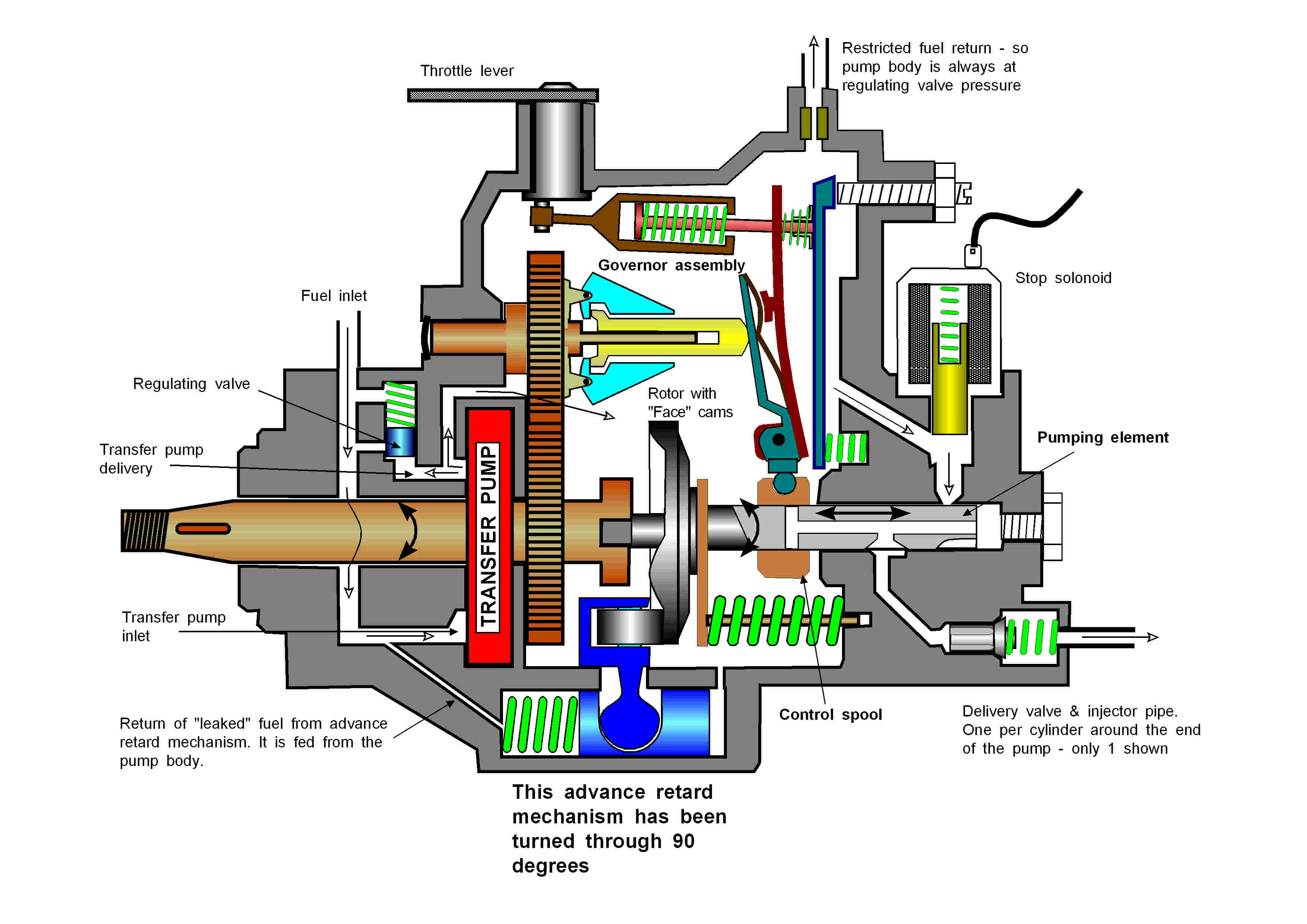
Governor
A typical centrifugal governor apart from the fact that the triangular bobweights are driven through a gear ratio. This has the effect of increasing the speed at which the governor spins which in turn produces more centrifugal force per engine rev. This increase in governor speed allows smaller and therefore lighter weights to be used and also reduces the inertia in the governor. The reduction in inertia makes the governor respond more quickly and helps to reduce surging.
Metering
The control of the amount of fuel injected and the distributor operation is described below.
The governor moves the control spool so the length of the injection stroke during which fuel can be pressurised is altered. At a certain point the port in the pumping element emerges from the control spool so the high pressure fuel can spill out into the pump body. thus stopping injection at that point.
Advance/Retard
Please note that the advance/retard mechanism has been turned through 90 degrees so you can see it on the diagram.
It operates in the same way as that on the DPA pump.
Stop control
This solenoid is energised when the "ignition" switch is turned on lifting the armature
clear of inlet to the pumping element.When the "ignition" is turned off the armature falls, blocking the inlet and thus preventing the delivery of high pressure fuel to the injectors.
Delivery valve
Similar in purpose and operation to those in the inline pump.
ADJUSTMENTS & SERVICE
The idle speed may have to be adjusted by the adjuster on the end of the pump body.
Do not attempt to adjust the maximum speed of an engine coupled to a generator.
Inspect for leaks & security.
INJECTORS
Introduction
Virtually all injectors used on small and medium sized industrial engines operate on the same principle. They may well look very different, but they all operate on a similar principle.
The end of the injector that is fitted into the combustion chamber, known as the nozzle, can be of several different designs which suit particular engine types.
Purpose
To deliver fuel into the CORRECT part of the combustion chamber as a finely atomised spray.
The high pressure reached during the compression stroke and the short time available for the fuel to be injected into the combustion chamber means that VERY HIGH pressures are used. A typical injector will be set to inject at a pressure 100 times greater than that used in a car tyre and for brief periods the pressure may well be 1000 times greater than normal tyre pressure.
Operation
Study the diagrams below
|
A Traditional injector |
A Modern injector |
The high pressure fuel enters the injector body it acts UPWARDS on the needle valve portion which is exposed to the annular fuel gallery in the nozzle. When the pressure acting on the needle valve overcomes the spring pressure the needle valve is forced up by a minute amount, this allows fuel to be injected from the nozzle.
The shape of the nozzle or nozzle and needle forms the spray of fuel into the required form.
The falling pressure at the end of injection allows the spring to force the needle back onto its seat in the nozzle.
Any fuel leaking past the needle is returned to the tank via the bleed off pipe, this should be a very small amount.
*** WARNINGS & SAFETY ***
OTHER INJECTORS
The older vehicles and many trucks use injectors that are located by one or two studs in the head (instead of being screwed into the head) and have their pressure set by a screw adjuster built as part of the upper body. These injectors use an identical operating
principle.Some injectors use two internal springs, these are known as two stage injectors. This design prevents the nozzle needle "bouncing" at the end of injection.
The nozzles also differ according to the engine application. These are illustrated on the next page
 |
Single hole nozzle
Used in direct injection engines. The spray pattern is a SOLID cone.
Multi-hole nozzle Also use in direct injection engines. The spray pattern is a number of solid cones. If the injector is mounted at an angle the sprays may appear to be at odd angles when tested.
Pintle nozzle Used in direct and indirect injection engines. The spray pattern is a hollow cone.
Pintaux nozzle Only used in indirect injection engines. Under normal running the spray pattern is a hollow cone. When the engine is starting (cranking) the pressure rise is slow so the needle does not fully lift. This allows the auxiliary spray hole to spray fuel into the hottest part of the chamber to aid cold starting.
|
STOP CONTROLS
There are three basic type of stop control:-
These have electricity supplied ONLY WHILE THE ENGINE IS BEING STOPPED and must be turned off as soon as the engine stops. Otherwise they will flatten the engine battery and possibly burn themselves out.
This uses electricity to lift a fuel cut off valve, so all the time the engine is running current is being supplied to the solenoid. When the engine is stopped current is cut off, so the valve falls (with spring assistance) and cuts off the fuel.
If one of these engines will not start remember to make sure the solenoid wire is still connected and that (with the "ignition" switch turned on) battery voltage is present at the terminal.
The solenoid can be unscrewed and a finger placed over the hole. If the engine then starts you know the valve was not lifting – but you will have to screw it back in to stop the engine!
You will need to turn the ignition ON before you can bleed an injector pump equipped with this type of stop control
Service
Lubricate mechanical parts.
Inspect terminals for security, tightness, and damage.
RUNAWAY ENGINES
At one time a type of governor known as a pneumatic governor was in common use. This used a throttle butterfly (like in a car’s carburettor) to produce a vacuum that in turn moved a diaphragm attached to the injector pump rack.
If the diaphragm got a puncture, or if someone inadvertently broke, split, or disconnected one of the pipes between the throttle butterfly housing and the injector pump, the rack would go to maximum fuel position and the engine run away. Sometimes the stop control would not work.
These engines are now rare, and as modern governors are enclosed within the pump and lubricated by clean fuel the chances of having an engine runaway are slim – whatever "bar stool Charlie" might tell you.
There are four other possible causes of runaway on modern engines:
Industrial engines have internal crank case breathers, so they burn the fumes that get past the piston into the crankcase. These breathers direct the fumes into the inlet manifold – hopefully via an oil & flame trap.
If the engine is overfilled, the amount of oil passing up the breather system can overwhelm the oil trap. This causes lubricating oil to be drawn into cylinder – and a diesel engine is just as happy running on lube oil as it is on diesel (and peanut oil, gas, coal dust etc).
If fuel leaks from an internal pipe into the sump the fuel will both raise the lubricating oil level and produce fumes when the engine is hot.
Again the breather system directs these fumes into the cylinders, allowing the engine to run on them.
If a sufficient concentration of flammable gas (butane, propane etc) gets into the air, the engine will burn this gas, again we get a runaway.
If you managed (and it’s a very big if – probably requiring sprays from cans) you managed to start an engine with badly worn pistons & bores, it could produce sufficient crankcase pressure to blow the lubricating oil through the breather.
However, I think the exhaust smoke and difficulty in starting might have warned you that something was going wrong.
How to stop a runaway.
The problem is that one has no way of knowing how fast the engine will run. If it revs too highly or for too long the big ends may very well snap, causing large chunks of metal and hot oil to fly out of the side of the engine. If something hit you in these circumstances it could do a serious injury.
Then problem is deciding how close to the engine you can get, and for how long.
My normal advice would be to get the engine under load (to try to hold the revs down a bit), turn off the main fuel tap, and retire to a safe distance. However this is probably not an option on a generator because using the generator to load a runaway engine could lead to over frequency and over voltage supplies that would damage a lot of electrical and electronic equipment.
If the engine is running on lubricating oil or gas you might not be able to stop it.
Once you have tried the normal stopping procedure, some ideas about stopping a runaway are detailed below (no particular order – choose the best one in the circumstances).
1. Let off a large CO2 fire extinguisher off into the air intake & hope that the extinguisher will last long enough to stop the engine by starving it of oxygen2. If the engine room is equipped with automatic CO2 fire extinguishers, let them off (remember that you must leave the room).
3. Place a very large wad of rag, rolled up into a ball, over the air intake. This might mean removing the air cleaner.4. Turn off the fuel supply and retire to a safe distance.
5. Slacken the injector pipes.
6. Undo a fuel supply pipe & retire (on a day tank system you must also turn the fuel tap off, otherwise you will have gas oil all over the floor!
7. Take an axe to a filter or fuel supply pipe - see above.
Whatever happens with a runaway, major engine damage or component strain must be suspected, so a strip-down would be indicated. It might be better just to turn the fuel off and retire.
I would once again stress that in over 40 years of dealing with diesels I have never known a mechanically or hydraulically governed one run away – I have heard lots of stories but am rather sceptical about them on modern engines.
| Home | Index |